Designing a wireless gesture recognition glove, part 2
September 9, 2013
This is the second part of the wireless glove series. Part one is here. Today, I’ll discuss schematic capture for the device.
Here is what the final schematic looks like:
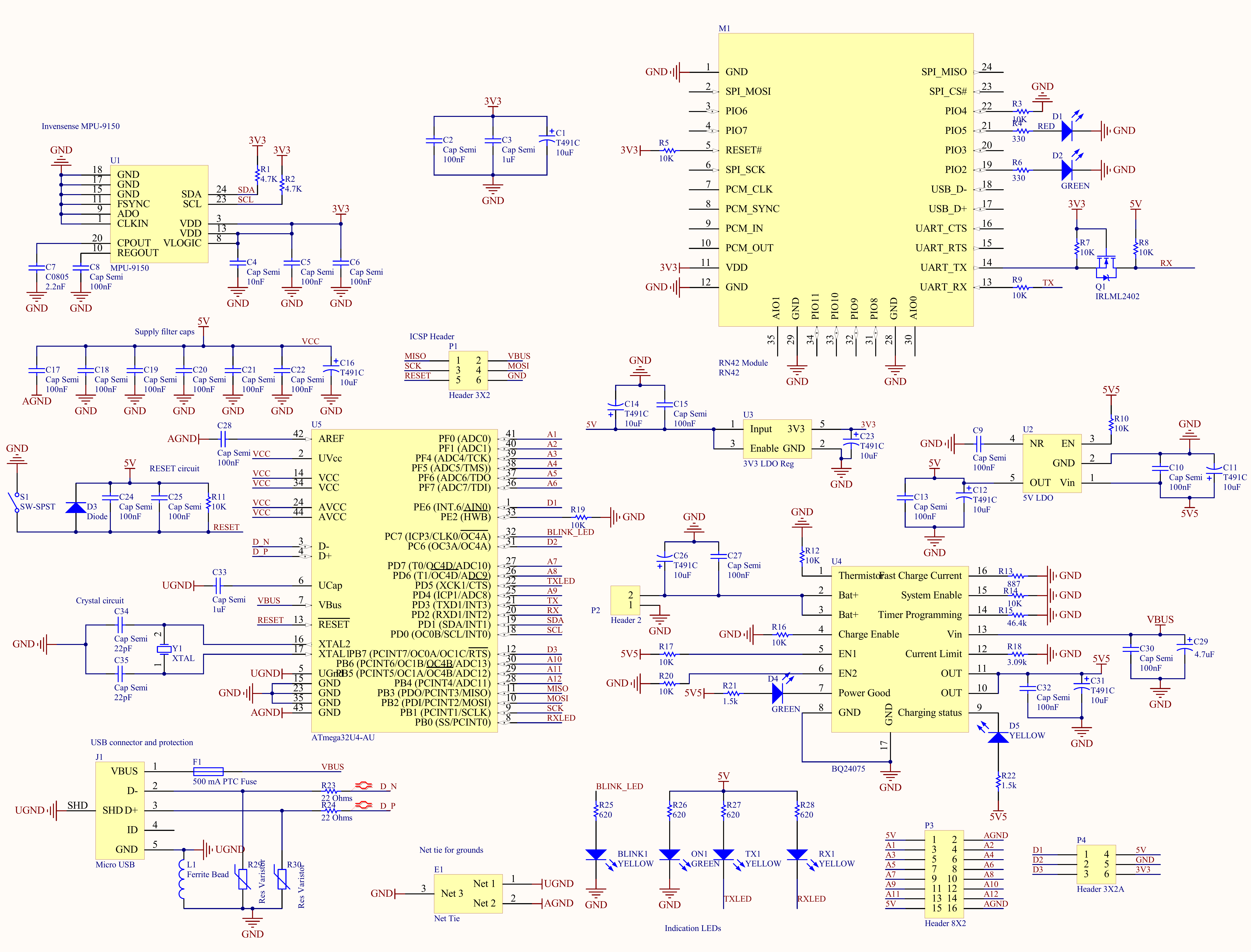

Microcontroller
Let’s start with the microcontroller and associated circuitry. I used the recommended 100nF ceramic caps next to the chip and a 10 uF tantalum for bulk capacitance to decouple the power supply. Next, I have a 16 MHz crystal and 22 pF crystal caps for a nice, stable clock source. Based on a few AVR Freaks threads, I’m only using an extra capacitor to filter AVCC compared to VCC which should be fine considering I don’t think I’ll need the last few bits of ADC resolution and I have lots of capacitance on the supply already. If we need more resolution, I’ll probably look at using an external ADC. I pull the bootloader pin (HWB) to GND to follow the arduino. The I2C lines head to the MPU-9150, the accelerometer/gyro/compass combo chip and the hardware UART pins go to the RN-42 Bluetooth module. A few lines go to various status LEDs while most are broken out to female headers for connection to the flex sensors and conductive pads on the glove. Lastly, I have an ICSP header for programming.
Reset
The reset circuit follows the Arduino as well. There’s a tactile switch for user reset with a 10K pull-up resistor to VCC. The diode protects against ESD. I notice now that the caps are wrong as they should be bypassing 5V to ground and not between the reset pin and 5V. Initially, I will just not populate those capacitors and if I do need them, I will solder one end to the right pad and jumper wire the other end to ground.
USB
For the USB connection which both powers and programs the board, I have two 1% 22 Ohm terminating resistors on the data line for impedance matching that connect directly to the microcontroller. The data lines also have a varistor each for ESD protection. There’s a 500 mA in-line PTC fuse on VBus to prevent blowing up the host’s USB port. The shield and USB ground connect to the board’s ground through a ferrite bead to block noise.
Sensor and Bluetooth
The Invensense MPU-9150 is pretty easy as it has a few decoupling caps, a few pins pulled to ground and the two I2C lines with 4.7K pullup resistors. The RN-42 module is also easy as it just has two status LEDs and decoupling caps. The one difference is that there is a level-shifting transistor on the (microcontroller) RX line to convert the 3V3 signal to a 5V signal.
Power
I’m using a TI BQ24075 to manage a 1-cell LiPo battery including automatically switching between charging and discharging based on the state of the cell and the input power. There’s a small terminal block for the battery input and two LEDs for indication. The BQ24075 has a built-in boost regulator which converts the input (either battery or USB) to a constant 5.5V output which makes voltage management a snap. There are two small LDO linear regulators on board, one for dropping 5V to 3V3 and one to drop 5.5V from the battery-management IC to 5V for the microcontroller. These have a few input and output bypass caps.
After schematic capture comes layout and in part 3, I’ll discuss my process for layout and component selection.