Raspberry Pi powered robotic bartender, part 2
January 23, 2014
This is the second post in a series about a Raspberry Pi based robotic bartender I’m building. The first is here. This post is on replacing the original solenoid control board with a custom PCB.
Design
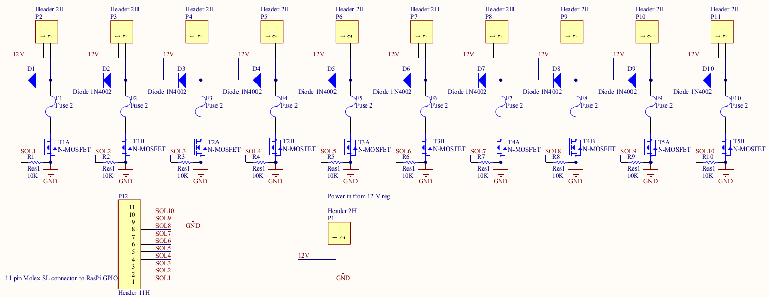
As described in the first post, the circuit to control the solenoids in extremely easy. There’s an N channel MOSFET on the low side to switch the solenoid and a flyback diode across the solenoid to prevent inductive voltage spikes. I especially wanted to bring the 12 V power onto the board so that the diodes could be placed on the board. In the current setup, they are spliced onto the middle of the wire which involved cutting the insulation on the middle of the wire. Finally, we need connectors from the board to the solenoids, power supply and Raspberry Pi. Finally there’s 10K pull downs on the gates to make sure they are always off during power up.
Here’s what the schematics look like:
Chip Selection
There’s not a whole lot that needs to be picked for the circuit. I chose 0805 resistors as space isn’t super tight and 0805 is a nice size to hand solder to and the cheapest general purpose surface mount diodes that can handle 1A. For the MOSFETs, I chose a two transistor 8-SOIC package because it costs less (~$0.45 for two MOSFETs, ~$0.40 for one) and is smaller than two discrete parts as I can’t solder the tiny SOT-323 packages. Finally, the solenoid and GPIO connectors are in the Molex SL family, which I really like as they are 0.100" pitch connectors and so mate with most hobbyist stuff.
Layout
Layout was very straight forward. There’s a row on the “north” side of 2 pin solenoid connectors, the circuit elements in the middle, and the 11 pin GPIO connector on the south side.
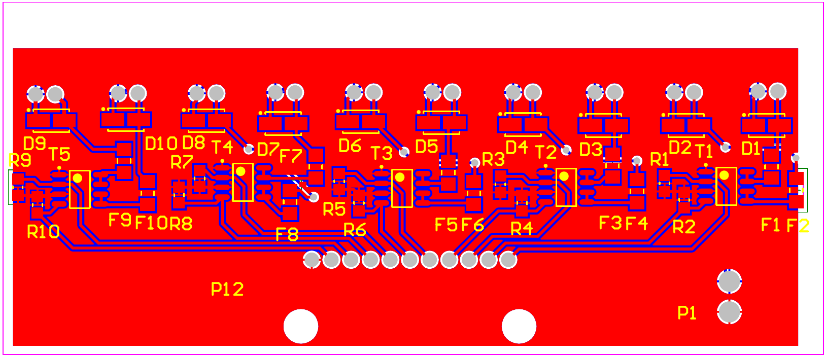
Now I’m just waiting for the parts to come in to check that the footprints to match the board and then it will get sent out to OSHPark to be fabbed.